
Professional Technical Guide Installation & Removal of QD and Taper Lock Pulley Systems

Professional Technical Guide: Installation & Removal of QD and Taper Lock Pulley Systems
Pulley systems are critical components in mechanical power transmission applications including motors, pumps, conveyors, and process machinery. This document provides professional-level procedural guidance for the installation and removal of QD (Quick Detachable) and Taper Lock pulley systems.
1. QD (Quick Detachable) Pulley System
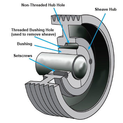
QD pulleys utilize a flanged, split-tapered bushing to secure the pulley to the shaft. This design promotes reliable clamping force, accurate positioning, and simplified removal.
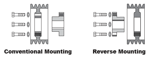
1.1 Mounting Configurations for QD Bushings
A. Conventional Mounting (Standard Orientation)
| Configuration Element | Description |
|---|---|
| Flange Position | Outward facing (visible and accessible) |
| Application | General machinery and standard maintenance environments |
| Serviceability | High – field access is simplified |
B. Reverse Mounting (Inverted Orientation)
| Configuration Element | Description |
|---|---|
| Flange Position | Inward, between pulley hub and equipment housing |
| Application | Compact machine layouts or restricted access conditions |
| Serviceability | Moderate – service may require extended tools or repositioning |
1.2 Installation Procedure – QD Pulley
Required Tools: Torque wrench, hex keys, anti-seize compound (threads only), emery cloth, PPE.
- Verify shaft and bushing compatibility; clean all surfaces.
- Insert bushing into pulley hub and install screws finger-tight only.
- Position assembly on the shaft (avoid impact or forced insertion).
- Progressively tighten screws in a cross-pattern to manufacturer torque specification.
- Verify alignment using straightedge or laser alignment tool.
- Run initial start-up and recheck torque after 10–15 minutes of operation.
1.3 Removal Procedure – QD Pulley
- Remove torque screws from mounting holes.
- Relocate screws to removal holes on the bushing.
- Tighten screws evenly until taper disengages.
- Withdraw pulley from shaft; avoid prying or metal hammer contact.
- Inspect component integrity before reinstallation or storage.
2. Taper Lock Pulley System
Taper Lock systems are engineered for precise concentricity at medium-to-high rotational speed applications. The bushing clamps concentrically around the shaft when mounting screws are torqued, providing high security and alignment accuracy.
2.1 Installation Procedure – Taper Lock
- Clean shaft, bushing, and pulley hub; ensure taper surfaces are dry (no lubrication).
- Insert bushing into pulley and secure screws finger-tight.
- Mount onto shaft and align key/keyway (where applicable).
- Tighten screws incrementally in an alternating pattern; apply final torque to specification.
- Confirm pulley alignment and perform trial run before load operation.
2.2 Removal Procedure – Taper Lock
- Remove all fastening screws.
- Insert screws into threaded release holes to disengage taper.
- Withdraw pulley from shaft without forceful prying.
- Inspect components prior to reuse.
3. Safety, Compliance & Engineering Considerations
| Requirement | Reason |
|---|---|
| Do not lubricate taper contact surfaces | Prevents slippage and torque failure |
| Mandatory torque wrench usage | Ensures proper clamping force |
| No direct hammer impact | Protects structural integrity of pulleys and bushings |
| Lockout/Tagout compliance | Ensures technician safety |
| Recheck torque after initial run | Compensates for thermal settling |
Conclusion
Correct installation and removal of QD and Taper Lock pulley systems ensures mechanical performance, alignment stability, and extended service life. By adhering to professional procedures, torque specifications, and engineering safety practices, downtime is reduced and asset reliability is improved. This guide establishes a professional standard for industrial maintenance and equipment servicing.
Dec 26,2025